Understanding Fills
Fills are used for fill settings. They are 2D geometric patterns that can be applied to all of ArchiCAD's construction and drawing objects (with the exception of lines). The main function of fills is to help distinguish the elements of the project. Fills are used in all 2D representation views (floor plans, sections, and elevations); in some cases they can also be displayed in 3D views. There are four types of fills (solid, vectorial, symbol, and image) that can be applied to objects in different contexts. These contexts have been organized into three categories, called Drafting Fill, Cover Fill, and Cut Fill. Every time you create or edit a fill (of any type), you will need to indicate in which contexts it can be used. There is a fourth type of context, called Vectorial 3D Hatching, which doesn't appear as an option in the regular fill-editing windows; it only appears if you want to link a fill to a material.
contexts where a fill can be applied ArchiCAD's drawing and construction objects are represented in different ways in your project's documentation, depending on the circumstances in which they are presented. To make it easier to control how objects are represented, ArchiCAD organized the use of fills into four types of context:
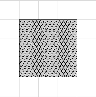
Drafting Fill (Drafting Fills): This classification is given to the fill of 2D drawing objects (rectangles, circles, polygons, etc.) that are used as auxiliary elements in project documentation. You can use any of the four fill types to fill a 2D object.
figure 1 - example of a 2D fill
Cover Fill (Cover Fills): This is the category given to a fill whenever it is used to represent construction objects (such as slabs, roofs, meshes, membranes, morphs, and zones) in floor plan views. The cover fill category is also used whenever you want to use a fill to represent construction elements in a 3D view. All four fill types can be used under the cover fill context.
Cut Fill (Cut Fills): This category appears whenever you need to indicate which fill will be used to represent a construction object when it is cut. To represent a construction object under the cut fill context, you can use a solid, vectorial, or symbol fill; you cannot use image fills. Vectorial 3D Hatching (Vectorial 3D Hatching): This category (which is well hidden in the program's menus) appears whenever you want to use a fill to represent a construction object that has not been cut, in section views, elevations, and perspectives. ArchiCAD normally uses an attribute called Material to represent construction objects in these views, so if you want to use a fill in these cases, it will be the one linked to the material applied to that object.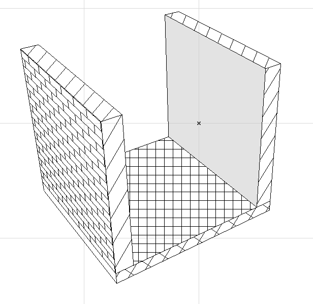 figure 2 - example of a cover fill applied to the surface of the slab, cut fills applied to the walls and the slab, and vectorial 3D hatching applied to the wall face.