How to create a terrain from the contour lines of a DWG
·3 min read
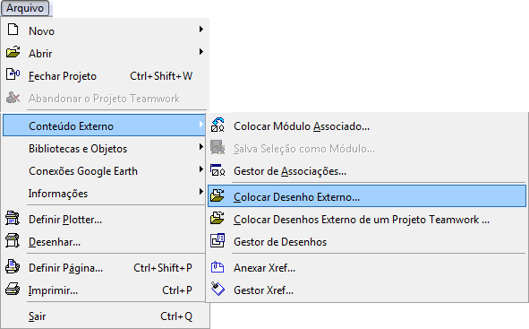
To create a terrain from the contour lines of a .dwg file, create a Worksheet and, in it, go to the File/External Content/Place External Drawing... (File/External Content/Place External Drawing...) menu.
figure 1 - how to import a .dwg file In the window that opens, choose the file to be imported and then click Open (Open). Next, select the drawing unit used in the original file and click Place (Place) to insert the drawing.
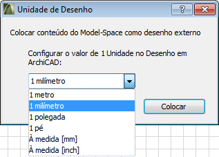 figure 2 - choosing the drawing unit of the .dwg file
Select the drawing you just imported and go to the Edit/Reshape/Explode into Current View (Edit/Reshape/Explode into Current View) menu, Ctrl + =.
 figure 3 - location of the Explode into Current View command
In the window that opens, click Keep drawing primitives only (Keep drawing primitives only) and then click on OK.
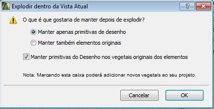 figure 4 - settings window for the Explode into Current View command
Go to the story where you want to model the terrain and activate the worksheet you created that contains the imported .dwg file as a Trace Reference.
In the Toolbox (Toolbox), click the Mesh tool
(Mesh).
figure 4 - settings window for the Explode into Current View command
Go to the story where you want to model the terrain and activate the worksheet you created that contains the imported .dwg file as a Trace Reference.
In the Toolbox (Toolbox), click the Mesh tool
(Mesh).
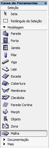 figure 5 - Mesh tool in the Toolbox
In the Info Box (Info Box), click the option that enables the Rectangular mesh. Open the Settings Dialog (Settings Dialog); on the Floor Plan and Section (Floor Plan and Section) tab, disable the Cover Fills (Cover Fills) option, highlighted in figure 6, and click OK.
figure 5 - Mesh tool in the Toolbox
In the Info Box (Info Box), click the option that enables the Rectangular mesh. Open the Settings Dialog (Settings Dialog); on the Floor Plan and Section (Floor Plan and Section) tab, disable the Cover Fills (Cover Fills) option, highlighted in figure 6, and click OK.
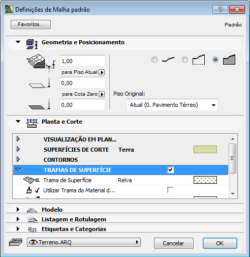 figure 6 - how to disable the surface fills of the mesh
With the modeled mesh selected and the Mesh (Mesh) tool still active, go to the Design/Outline Polygon with Magic Wand menu (or press the space bar) (Design/Outline Polygon with Magic Wand) and select one of the contour lines.
figure 6 - how to disable the surface fills of the mesh
With the modeled mesh selected and the Mesh (Mesh) tool still active, go to the Design/Outline Polygon with Magic Wand menu (or press the space bar) (Design/Outline Polygon with Magic Wand) and select one of the contour lines.

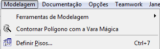 figure 7 - selecting the contour line figure 8 - location of the Magic Wand command
In the window that opens, select Add New Points and choose the Fit to User Edges (Fit to Users Ridges) option. Click OK. This makes ArchiCAD use the line from the DWG drawing to create the corresponding contour line on your mesh. Repeat this procedure for all the contour lines.
figure 7 - selecting the contour line figure 8 - location of the Magic Wand command
In the window that opens, select Add New Points and choose the Fit to User Edges (Fit to Users Ridges) option. Click OK. This makes ArchiCAD use the line from the DWG drawing to create the corresponding contour line on your mesh. Repeat this procedure for all the contour lines.
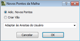 figure 9 - New Mesh Points menu
Now you will need to tell ArchiCAD the height of each contour line. To do this, click any point on the curve for which you want to set the elevation and, in the floating toolbar, click the Elevate Mesh Point... (Elevate Mesh Point) button.
figure 9 - New Mesh Points menu
Now you will need to tell ArchiCAD the height of each contour line. To do this, click any point on the curve for which you want to set the elevation and, in the floating toolbar, click the Elevate Mesh Point... (Elevate Mesh Point) button.
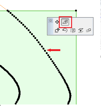 figure 10 - select any point on the contour line
Set the height of the point you clicked and enable the Apply to All (Apply to All) option, then click OK. Repeat the procedure for all the remaining curves.
figure 10 - select any point on the contour line
Set the height of the point you clicked and enable the Apply to All (Apply to All) option, then click OK. Repeat the procedure for all the remaining curves.
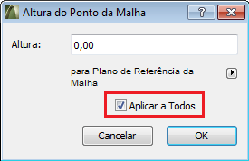 figure 11 - Mesh Point Height menu
If you want to adjust the terrain point by point, go to the Navigator/Project Map (Navigator - Project Map) palette and click Generic Perspective (Generic Perspective); then click the point you want to move and see the change caused in the terrain.
figure 11 - Mesh Point Height menu
If you want to adjust the terrain point by point, go to the Navigator/Project Map (Navigator - Project Map) palette and click Generic Perspective (Generic Perspective); then click the point you want to move and see the change caused in the terrain.
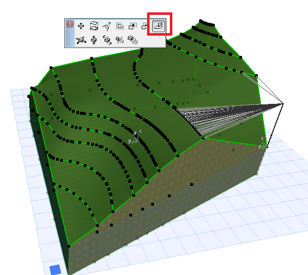 figure 12 - 3D terrain modeling.