How to Create a Terrain
·2 min read
There are several ways to create a 3D terrain in Vectorworks. You can import a file with topography data, use the grid data-entry method, or use terrain contour lines (which is the most commonly used method and the one explained here). Once the 3D contours have been created, the terrain is generated as a parametric object, which can be edited at any time through the Object Info (Object Info) palette, Ctrl+I. The explanations below are based on the Architect workspace, present in both the Brazilian and American versions of Vectorworks.
to create 3D contour lines from 2D polygons or polylines
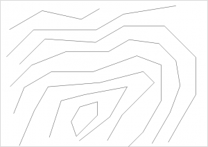
Create a layer just to hold the terrain's contour lines (you can draw them, bring them in from another Vectorworks file, or import them from a survey done in AutoCAD, for example) (figure 1).
 figure 1
Go to the menu (AEC/Survey Input/2D Polys to 3D Contours....) (figure 2)
figure 1
Go to the menu (AEC/Survey Input/2D Polys to 3D Contours....) (figure 2)
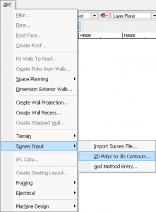 figure 2
Indicate the terrain's starting elevation and the interval between the layer's contour lines (figure 3).
figure 2
Indicate the terrain's starting elevation and the interval between the layer's contour lines (figure 3).
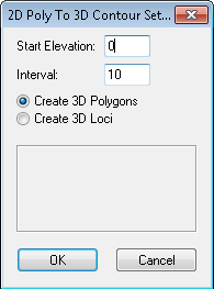 figure 3
Choose the (Create 3D Polygons) option as the result of the contour line operation. Click OK.
At this point, the program selects one of the drawing's curves, highlighted in red. In the panel, indicate the elevation of the highlighted curve using the Up and Dn buttons (raise and lower). Once you find the correct value, click Next, and Vectorworks will move on to the next curve. If you want to use the same value as the previous curve for the current one, click Use same height as prev.. If you want to finish the operation without setting all the elevations, click Done (figure 4).
figure 3
Choose the (Create 3D Polygons) option as the result of the contour line operation. Click OK.
At this point, the program selects one of the drawing's curves, highlighted in red. In the panel, indicate the elevation of the highlighted curve using the Up and Dn buttons (raise and lower). Once you find the correct value, click Next, and Vectorworks will move on to the next curve. If you want to use the same value as the previous curve for the current one, click Use same height as prev.. If you want to finish the operation without setting all the elevations, click Done (figure 4).
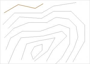
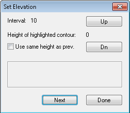 figure 4
After you finish setting the elevations, the program asks whether you want to delete the original polygons. If you no longer need them, answer Yes. If you want to keep them for some future modification, click No (figure 5).
figure 4
After you finish setting the elevations, the program asks whether you want to delete the original polygons. If you no longer need them, answer Yes. If you want to keep them for some future modification, click No (figure 5).
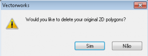 figure 5
NOTE 1 If possible, use only 2D polygons to create the contour lines. 2D polylines, which can work with curves, add a large number of vertices to the 3D contour line, making the file heavier and slower.
NOTE 2 The original 2D contour lines cannot cross each other. Overlapping polygons prevent the 3D terrain from being displayed correctly.
Did you like this post?
It was based on the topic Digital terrain modeling, How to create a terrain,
which is part of the book Vectorworks passo a passo,
available in print or e-book.
For more information or to purchase the book,
visit the site www.probooks.com.br
figure 5
NOTE 1 If possible, use only 2D polygons to create the contour lines. 2D polylines, which can work with curves, add a large number of vertices to the 3D contour line, making the file heavier and slower.
NOTE 2 The original 2D contour lines cannot cross each other. Overlapping polygons prevent the 3D terrain from being displayed correctly.
Did you like this post?
It was based on the topic Digital terrain modeling, How to create a terrain,
which is part of the book Vectorworks passo a passo,
available in print or e-book.
For more information or to purchase the book,
visit the site www.probooks.com.br
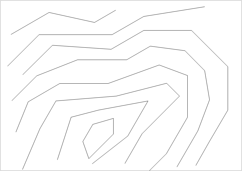 figure 1
Go to the menu (AEC/Survey Input/2D Polys to 3D Contours....) (figure 2)
figure 1
Go to the menu (AEC/Survey Input/2D Polys to 3D Contours....) (figure 2)
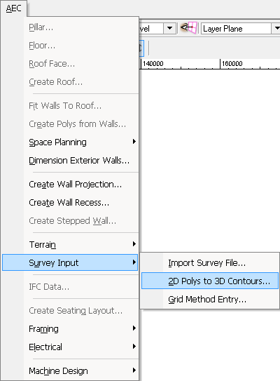 figure 2
Indicate the terrain's starting elevation and the interval between the layer's contour lines (figure 3).
figure 3
Choose the (Create 3D Polygons) option as the result of the contour line operation. Click OK.
At this point, the program selects one of the drawing's curves, highlighted in red. In the panel, indicate the elevation of the highlighted curve using the Up and Dn buttons (raise and lower). Once you find the correct value, click Next, and Vectorworks will move on to the next curve. If you want to use the same value as the previous curve for the current one, click Use same height as prev.. If you want to finish the operation without setting all the elevations, click Done (figure 4).
figure 2
Indicate the terrain's starting elevation and the interval between the layer's contour lines (figure 3).
figure 3
Choose the (Create 3D Polygons) option as the result of the contour line operation. Click OK.
At this point, the program selects one of the drawing's curves, highlighted in red. In the panel, indicate the elevation of the highlighted curve using the Up and Dn buttons (raise and lower). Once you find the correct value, click Next, and Vectorworks will move on to the next curve. If you want to use the same value as the previous curve for the current one, click Use same height as prev.. If you want to finish the operation without setting all the elevations, click Done (figure 4).
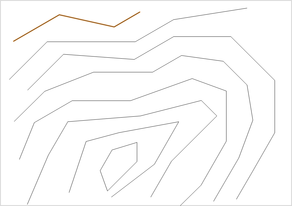 figure 4
After you finish setting the elevations, the program asks whether you want to delete the original polygons. If you no longer need them, answer Yes. If you want to keep them for some future modification, click No (figure 5).
figure 4
After you finish setting the elevations, the program asks whether you want to delete the original polygons. If you no longer need them, answer Yes. If you want to keep them for some future modification, click No (figure 5).
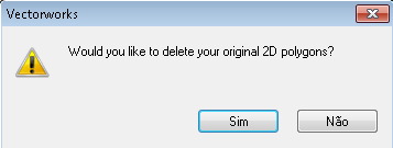 figure 5
NOTE 1 If possible, use only 2D polygons to create the contour lines. 2D polylines, which can work with curves, add a large number of vertices to the 3D contour line, making the file heavier and slower.
NOTE 2 The original 2D contour lines cannot cross each other. Overlapping polygons prevent the 3D terrain from being displayed correctly.
Did you like this post?
It was based on the topic Digital terrain modeling, How to create a terrain,
which is part of the book Vectorworks passo a passo,
available in print or e-book.
For more information or to purchase the book,
visit the site www.probooks.com.br
figure 5
NOTE 1 If possible, use only 2D polygons to create the contour lines. 2D polylines, which can work with curves, add a large number of vertices to the 3D contour line, making the file heavier and slower.
NOTE 2 The original 2D contour lines cannot cross each other. Overlapping polygons prevent the 3D terrain from being displayed correctly.
Did you like this post?
It was based on the topic Digital terrain modeling, How to create a terrain,
which is part of the book Vectorworks passo a passo,
available in print or e-book.
For more information or to purchase the book,
visit the site www.probooks.com.br